|
Technology at Work There are essentially three means available for engine temperature stabilization: a direct driven mechanical fan, a thermostatically modulated mechanical fan, and an electric motor driven fan. In a typical application of a direct driven mechanical fan, about 15 HP is a consumed at maximum engine RPM. Moreover, as RPM increases, windage loss will increase at a cubed law rate. In other words, an increase in rotational speed from 5000 RPM to 6000 RPM will increase windage loss by a factor of (6/5)3 or 1.7:1. A thermostatically modulated fan performs well under steady state conditions such as highway driving. On the other hand, during transient load conditions, such as a 1/4 mile run, the performance is similar to that of a direct driven fan as the rate of modulation is limited byway of the heat capacity of the mechanical clutch. An electric fan is most efficient, a typical application drawing less than one horsepower. Moreover, modern electric fans have the capacity to control temperatures in almost any application.
Reliability Unlike the majority of aftermarket products, the Delta controller is designed and manufactured with reliability in mind. Not only are die temperatures kept low to insure long life, a multitude of safety and reliability features, some not even available on OEM products are employed: Over current, short circuit and over / under voltage protection limit the inrush current to the load, providing protection for not only the controller, but to the fan and to the remainder of the electrical system as well. Over temperature monitoring provides multi-step protection. Under moderately severe conditions, output current is progressively reduced, causing only a subtle rise in engine temperature. Where more severe conditions are introduced, the control unit will begin to cycle in a fashion similar to a standard controller. This provides not only protection for the controller but also acts as a problem indicator to the driver as cooling noise will substantially increase. Finally, if conditions prove to be too severe for safe operation, the controller will shut itself off.
High current 3M connectors are utilized in our 10-gauge copper, multi-strand wiring loom. The loom comprises crosslinked polyethylene insulating material, which is abrasion resistant, specified over a -51°C to +125°C temperature range and meets both Ford (M1L-85A) and Chrysler (MS-5919) specifications as well as Society of Automotive Engineer’s SAE J-1128 specification for high temperature engine compartment applications. This is not the case for the majority of aftermarket components. Economic Value Elimination of secondary failures A Consumers digest report, "How to make your car last 200,000 miles", revealed the most common automotive failures. Cooling system components topped the list and included both radiator and head gasket failure. Modern cooling systems are pressurized in order to prevent boil over, typical pressures being between 12 and 18 psi. Due to the fact that liquids are inherently non-compressible, a change in engine temperature of only a few degrees Fahrenheit will result in a full decompression of the cooling system. While the pressures involved are rather low when compared to other systems, the resulting force, and more importantly, the change in force over time exerted on system components is exceptionally high. The surface area of the front or rear side of a typical radiator tank, for example, measures approximately 80 square inches. Fifteen pounds per square inch of pressure will distribute approximately 1200 lbs of force over the area described. Although certain alloys of aluminum result in fairly tough materials, less rugged metals such as the 1100 or 3000 series of aluminum are used in radiator construction for their thermal conduction properties. Brass, also alloyed for thermal performance in lieu of strength, is employed in the construction of radiators as well. These trade offs result in materials which readily work harden and become brittle to the point of failure as varying pressures cycle the distortion of the radiator structure. While the advent and use of ethylene glycol has solved the corrosion means of head gasket deterioration, the loss of sealing capacity has continued to be a source for high failure rates, most notably in the 3.8L Ford V6. These failures are a result of the design, inherently bound by a set of compromises, of the combustion chamber sealing mechanism in that there are essentially two mutually exclusive means of attaining an air tight seal; elasticity and malleability, also known as cold flow sealing. Modern engine designs employ close cylinder to cylinder spacing for both weight savings and spatial efficiency and for this reason, a malleable copper-fibre composite is utilized to seal the combustion chamber. The combination of thin-walled, non resilient gasket material, numerous thermal expansion coefficients of metals employed in various engine components, and the continuous thermal cycling of these materials provide an obvious mechanism of failure. Reduction in secondary costs Often Increased electrical current requirements require an alternator upgrade. It may be possible to forgo this cost by installing a variable speed controller. This is due to the fact that the amount of power needed in order to move a given amount of air is a function of the resulting change in kinetic energy ((1/2)mV2), where m represents the mass of air moved and V represents the change in velocity. In other words, as in all cases, the energy input is equal to the energy output. The amount of power needed (energy with respect to time) in order to move an amount of air over a specified duration is equal to (1/2)mV2/t. If the cfm output of a fan is reduced to, as an example to 63% of full output, the mass moved per time is 63% of the full cfm rate. The resulting velocity is also 63% of the original velocity. The needed power input as a percentage of full power is then [(.63/2)m(.63V)2)/t / (1/2)m(V)2/t ] = (.63)3 or 25%. The table below shows average current consumption verses percent cfm and the relative efficiency of a variable system with respect to a switched system.
The criterion for selecting alternator current capabilities is based on the worst-case current consumption. Both average and peak current need to be considered as the average current determines the long term degradation of the component, while a high peak current is often responsible for failures that are well within the service life of the alternator While the short term peak current of a fan is typically three times the running current and lasts between one and five seconds subsequent to turning on the fan byway of a relay, the Delta controller slowly ramps up the voltage to a fan so that this peak current does not occur. A typical worst-case set of conditions would occur during a warm night. The table below illustrates a typical worst-case state of average, long term peak, and short term peak current consumption. The on time for a 40 A fan is assumed to be 50%.
Although the average current is 15 % lower, the long term peak current (> 30 sec) is 28% lower and the absolute peak current is 54% lower with the variable controller. |
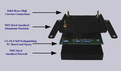 For
added safety, a UL-94-0 self-extinguishing PC board, encapsulated within a
high-grade epoxy, also UL-94-0 rated, is housed in an aircraft grade 5052
hard-anodized aluminum fire resistant housing.
For
added safety, a UL-94-0 self-extinguishing PC board, encapsulated within a
high-grade epoxy, also UL-94-0 rated, is housed in an aircraft grade 5052
hard-anodized aluminum fire resistant housing.