|
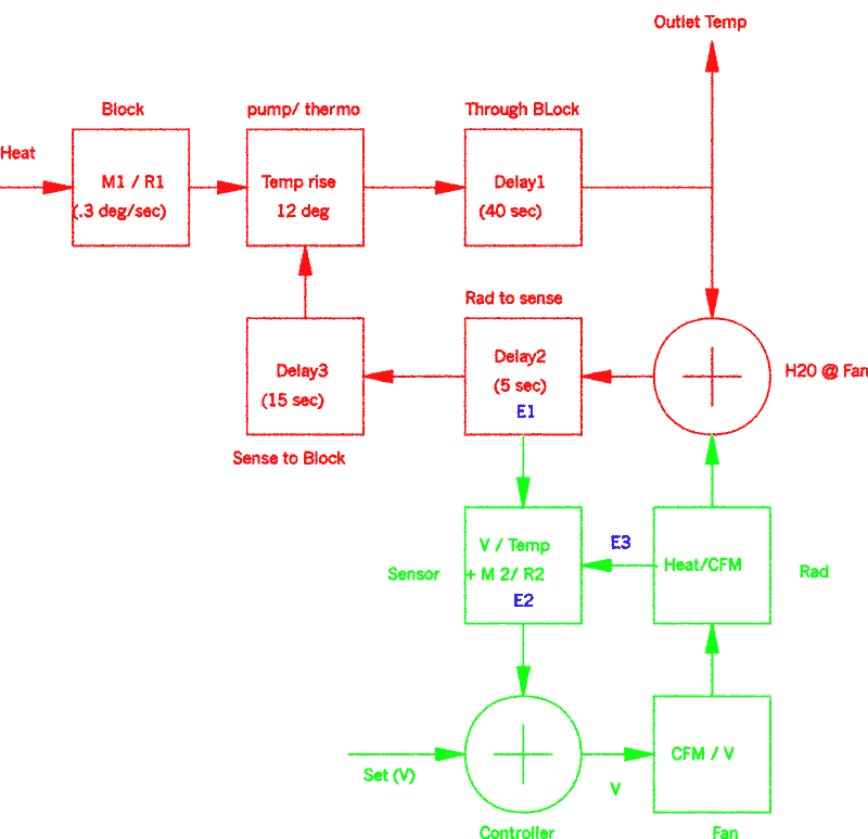
The diagram above shows the operation of the FK series controllers. The mechanical related components are shown in red and the controller related components are shown in green.
From the left, the heat of combustion enters the block byway of the combustion medium., the thermal resistance of the mixture provides a slow rise in temperature on the order of .3 degrees per second. The coolant flows through the block in order to scavenge heat to be transferred to the radiator, as the temperature of the coolant moves through the block its temperature rise is influenced by the flow rate of the coolant, the heat capacity of the coolant, and the heat generated. An underdrive pulley set will increase the temperature rise by about 4 degrees, as will a high mixture of antifreeze. With the combination of the two, a one step lower temperature setting of the controller will offset any deviation from the 12 degree rise. It should also be noted that a closed thermostat will also increase the temperature rise.
The coolant takes approximately 40 seconds to travel through the block and to the radiator before the heat is transferred to the radiator where the heat is removed from the system. The heat is removed from the coolant byway of the radiator and fan and another, much shorter delay occurs before the temperature is sensed. Finally, a third delay, from the radiator to the block occurs and then the cycle repeats. The sensor measures the temperature of the coolant at the radiator output and converts the temperature to a tracking voltage; the controller then compares this voltage to the set voltage (jumpers), and outputs a control voltage to the cooling fan that is proportional to the difference in these voltages. Finally, the fan pulls that heat from the radiator in order to keep the coolant at the set temperature. Because the temperature rise through the engine is constant, a 12 degree sensing offset at the controller keeps the engine outlet temperature at the controller set point.
The delay from the coolant at the fan to the coolant at the probe causes a delay in the reaction time of the controller. This error, E1, is significantly small, given that the rise in temperature is only .3 degrees per second. Although this would appear to provide a 1.5 degree overshoot in temperature, the error occurs at the bottom of the ramp up of the controller, which is typically three degrees lower than the running temperature, so no overshoot occurs. Even with a 25% decrease in the rate of coolant flow, which is typical when using underdrive pulleys, the overshoot is only 2 degrees, which is still lower than the three degrees mentioned earlier.
A second error, E2 will occur if the probe is not well thermally coupled to the radiator. Placing the sensor from the front of the radiator will also cause this problem when slowing from freeway speeds, due to the fact that the probe and the most forward radiator fins will be cooled far below the coolant temperature from the airflow. When the car comes to a stop, the probe temperature needs to rise from ambient to the coolant temperature, which takes time and causes a temperature overshoot, so the sensor should always be placed on the engine side of the radiator
Finally, a third error E3 occurs if the probe is cooled directly by the fan. The result of this error is a decrease in the loop gain of the system, in that the full-off to full-on temperature range will increase. Placing the sensor towards the corner of the radiator, however, renders this error insignificant.
Setting the temperature lower than that of the mechanical thermostat will cause the thermostat to close and will result in an increase in the time delay (E1) significantly enough to cause a delay in the starting of the fan and a subsequent overshoot in the fan speed and although this will effect the temperature stability to some degree by causing the thermostat to cycle, the main effect will be an increase in the perceived fan noise. A second order temperature variance will also result byway of the hysteresis of the mechanical thermostat.
Because the design results in very low measurement errors, a very stable engine temperature, void of any heat cycling with a full-off to full-on variance of only seven degrees is typical. |
