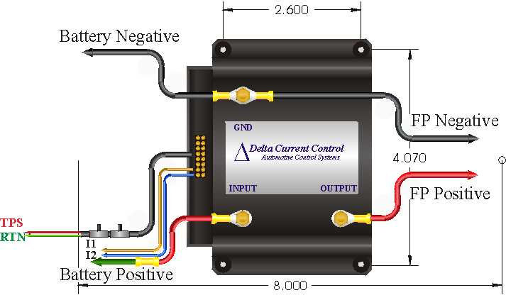
Turn on the ignition switch.
Adjust the single potentiometer for the desired closed-throttle power setting, Open the throttle from zero to
the desired controller full-power position and adjust the dual potentiometer for
100%, the fuel pump speed should ramp
up linearly with the throttle position.
Delta Current
Control, hereon referred to as DCC, warrants to the first consumer purchaser
that this DCC brand product, hereon referred to as the product, when shipped in
its original container, will be free from defective workmanship and materials
and agrees to, at its option, either repair the defect or replace the defective
Product or part thereof at no charge to the purchaser for parts or labor for the
time period(s) set forth below.
This warranty does
not apply to any appearance items of the Product nor to any product the exterior
of which has been damaged or defaced, which has been subjected to misuse,
abnormal service or handling or which has been altered or modified in design or
construction.
In order to enforce
the rights under this limited warranty, the purchaser should follow the steps
set forth below and provided proof of purchase to the servicer.
The limited
warranty described herein is in addition to whatever implied warranties may be
granted to purchasers by law. ALL IMPLIED WARRANTIES INCLUDING THE WARRANTIES OF
MERCHANT ABILITY AND FITNESS FOR USE ARE LIMITED TO THE PERIOD"(S) FROM THE DATE
OF PURCHASE SET FORTH BELOW. Some states do not allow limitations on how long an
implied warranty lasts, so the limitation may not apply to you.
Neither the sales
personnel of the seller nor any other person is authorized to make any
warranties other than those described herein or to extend the duration of any
warranties beyond the time period described on behalf of DCC.
The warranties
described herein shall be the sole and exclusive warranties granted by DCC and
shall be the sole and exclusive remedy available to the purchaser. Correction of
defects, in the manner and for the period of time described herein, shall
constitute complete fulfillment of all liabilities and responsibilities of DCC
to the purchaser with respect to the Product and shall constitute full
satisfaction of all claims, whether based on contact, negligence, strict
liability or otherwise. In no event shall DCC be liable, or in any way
responsible, for any damages or defects in the Product which were caused by
repairs performed by anyone other than an authorized servicer. Nor shall DCC be
liable, or in any way responsible, for any incidental or consequential economic
or property damage. Some states do not allow the exclusion of incidental or
consequential damages, so the above exclusion may not apply to you.
THE WARRANTY GIVES
YOU SPECIFIC LEGAL RIGHTS. YOU MAY ALSO HAVE OTHER RIGHTS WHICH VARY FROM STATE
TO STATE.
|
Warranty Period for this Product: |
Ninety (90) days parts and labor
from date of purchase |
|
Where to obtain service:
|
To locate an
authorized DCC service center, contact Delta Current Control at (408) 379 -
8951 |
