Figure 1a
Delta Temp Probe
Figure 1b
Down Flow Radiator
Figure 1c
Cross Flow Radiator
FK-50P 50A
Fan Control Kit
Delta Current Control module
Installation
Setting the Jumpers
If underdrive pulleys are installed and the vehicle is prone to overheating at idle, a jumper is provided (13,14) to render a 10 % minimum current to the fan whenever the ignition is on in order to aid in convection flow. The ignition input wire must be connected to use this feature.
Setting the Temperature
The controller is set from the factory for use with a 180 degree thermostat, the set temperature, however, can be adjusted byway of the multiturn potentiometer. Each turn clockwise will raise the temperature approximately 3 1/2 degrees, each turn ccw will lower the temperature by the same amount. A total adjustment of +/- 35 degrees is possible.
Mounting the control unit
Find a flat surface in the engine compartment, the preferred area being the radiator support sheet metal near the battery. Drill four 1/8" holes either by the dimensions shown in figure 2 or by using the control unit as a template. Drill two more 1/8" holes at about 8" centers as shown in figure 2. If installed in a detailed engine compartment, insert the four grommets in the mounting holes of the control unit to protect painted surfaces. Mount the control unit using four self tapping screws and flat washers.
Delta fast response temperature sensor
Mounting the temperature sensor
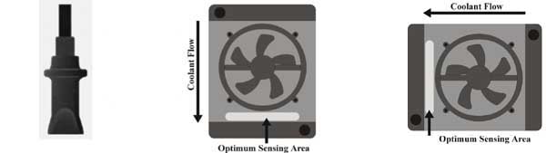
Figure 1a shows the Delta temperature probe. Its low mass, high friction housing and high flex multi strand wiring loom provide a fast response time and convenient mounting, requiring no retaining mechanism. Simply insert the probe between the radiator fins and the mounting is complete. Unlike other control systems, the DCC fan control operates most accurately when the temperature is indicated downstream from the cooling fan.
Down flow radiator positioning
Figure 1b shows the correct mounting position on a conventional radiator. Mounting is below the fan, and near the outlet hose.
Cross flow radiator positioning
Figure 1c shows the correct mounting position on a cross flow radiator. Mounting is to the side of the fan, and near the radiator outlet hose.
|
Figure 1a Delta Temp Probe |
Figure 1b Down Flow Radiator |
Figure 1c Cross Flow Radiator |
|
|
||
Control unit wiring
High current wiring
Plug the mounted sensor into pins 1, 2 of the control unit.
Using the supplied wiring loom, secure one connectored end of the red wire on the
Place one connectored end of the black wire on the GND terminal of the controller. Route the wire to the negative fan terminal, cut and trim the wire and install the butt connector to connect the fan wiring.
Place the connectored end of the remaining black wire on the GND terminal of the controller and secure both wires with one star washer and 6-32 brass hex nut. Route the wire to the negative battery terminal. Attach the 5/16 ring terminal and connect to the negative battery terminal.
Place the connectored end of the remaining red wire on the
Figure 2
 |
Auxiliary wiring
AC input
|
|
|
Parts List 1 control unit 1 radiator temperature probe 1 high current wiring harness 1 low current wiring harness 1 fusible link 2 controller to fan connectors1 U/D jumper |
1 5/16 ring terminal 2 wire hold downs 3 internal star washers 3 6-32 brass nuts 6 # 6 self tapping screws 6 flat washers 4 3/16 rubber grommets |
|
Testing the unit
Start the car. If equipped with air conditioning, turn on the AC, the fan should run at 50 % power without the underdrive jumper and 100% with the jumper. Check the direction of airflow and reverse the fan input wires if necessary. Turn off the AC and let the engine warm up. The fan should run at the necessary speed to stabilize engine temperature.