|
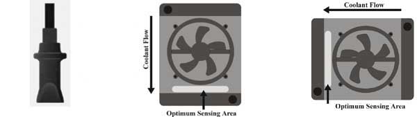
Figure 1a Delta Temp Probe |
Figure 1b Down Flow Radiator |
Figure 1c Cross Flow Radiator |
|
|
||
FK-60 60A
Fan Control KitInstallation
Setting the Jumpers
Temperature
The Delta controller is factory set to operate with a 180° thermostat, the unit temperature can be adjusted byway of jumpers. Jumpers (5,7) and (6,8) raise the temperature by 22° and 14° respectively. Jumpers (7,9) and (8,10) lower the temperature by 22° and 14° respectively. The chart in figure 2 shows jumper settings for various temperatures.
Underdrive
If underdrive pulleys are installed and the vehicle is prone to overheating at idle, a jumper is provided (13,14) to render a 10 % minimum current to the fan whenever the ignition is on in order to aid in convection flow. The ignition input wire must be connected to use this feature.
Mounting the control unit
Find a flat surface in the engine compartment, the preferred area being the radiator support sheet metal near the battery. Drill four 1/8" holes either by the dimensions shown in figure 2 or by using the control unit as a template. Drill two more 1/8" holes at about 8" centers as shown in figure 2. If installed in a detailed engine compartment, insert the four grommets in the mounting holes of the control unit to protect painted surfaces. Mount the control unit using four self tapping screws and flat washers.
Delta fast response temperature sensor
Mounting the temperature sensor
Figure 1 a shows the Delta temperature sensor. Its low mass, high friction housing and high flex multi strand wiring loom provide a fast response time and convenient mounting, requiring no retaining mechanism. Simply insert the sensor from the engine side between the radiator fins to the point that the ridge on the back of the sensor is flush with the radiator fins and the mounting is complete. Unlike other control systems, the DCC fan control operates most accurately when the temperature is indicated downstream from the cooling fan
Down flow radiator positioning
Figure 1b shows the correct mounting position on a conventional radiator. Mounting is below the fan, and near the outlet hose.
Cross flow radiator positioning
Figure 1c shows the correct mounting position on a cross flow radiator. Mounting is to the side of the fan, and near the outlet hose.
|
Figure 1a Delta Temp Probe |
Figure 1b Down Flow Radiator |
Figure 1c Cross Flow Radiator |
|
|
||
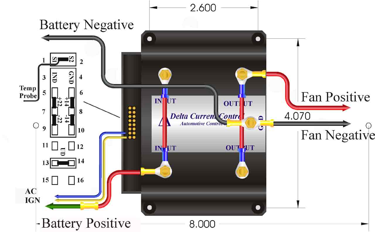
Control unit wiring
High current wiring
Plug the mounted sensor into pins 1, 2 of the control unit.
Using the supplied wiring loom, secure one connectored end of the red wire on the
Place one connectored end of the black wire on the GND terminal of the controller. Route the wire to the negative fan terminal, cut and trim the wire and install the female fastconnect. Connect the fan.
Place the connectored end of the remaining black wire on the GND terminal of the controller and secure both wires with one star washer and 6-32 brass hex nut. Route the wire to the negative battery terminal. Attach the 5/16 ring terminal and connect to the negative battery terminal.
Place the connectored end of the remaining red wire on the
Figure 2
|
CAUTION INSERTING A JUMPER ACROSS PINS 11 and 12 WILL DAMAGE THE CONTROL UNIT |
|
Auxiliary wiring Ignition input For continued cooling after engine shut-off, connect the yellow ignition input wire of the harness to the unit and to any 12 V source. If an Immediate shut off is required, connect the yellow ignition input wire of the harness to the unit and to any source that is 12 V whenever the the ignition is on. AC input If the vehicle has air conditioning and a factory installed electric fan, connect the blue AC input wire of the harness to the unit and to the positive terminal of the OEM fan wiring harness. If the vehicle has air conditioning and originally came with a mechanical fan, connect the blue AC input wire of the harness to the air conditioning compressor input. |
|
148 |
158 |
166 |
173 |
180 |
187 |
194 |
202 |
212 |
|
|
(5,7) |
· |
· |
· |
||||||
| (6,8) |
· |
· |
· |
||||||
| (8,10) |
· |
· |
· | ||||||
| (7,9) |
· |
· |
· |
|
Parts List 1 control unit 1 radiator temperature probe 1 high current wiring harness 1 low current wiring harness 2 fastconnect harnesses 1 fusible link 2 female fastconnects 2 male fastconnects |
1 5/16 ring terminal 2 wire hold downs 3 internal star washers 3 6-32 brass nuts 6 # 6 self tapping screws 6 flat washers 3 zero ohm jumpers 4 3/16 rubber grommets |
Testing the unit
Start the car. If equipped with air conditioning, turn on the AC, the fan should run at 50 % power without the underdrive jumper and 100% with the jumper. Check the direction of airflow and reverse the fan input wires if necessary. Turn off the AC and let the engine warm up. The fan should run at the necessary speed to stabilize engine temperature.
WP-35 35A Water Pump Control Kit
Installation
Setting the Jumpers
Temperature
The Delta controller is factory set to operate with a 180° thermostat, the unit temperature can be adjusted byway of jumpers. Jumpers (5,7) and (6,8) raise the temperature by 22° and 14° respectively. Jumpers (7,9) and (8,10) lower the temperature by 22° and 14° respectively. The chart in figure 2 shows jumper settings for various temperatures.
Underdrive
Connect the provided jumper(13,14) to render a 10 % minimum current to the water pump whenever the ignition is on in order to provide a nominal flow. The ignition input wire must be connected to use this feature.
Mounting the control unit
Find a flat surface in the engine compartment, the preferred area being the radiator support sheet metal near the battery. Drill four 1/8" holes either by the dimensions shown in figure 2 or by using the control unit as a template. Drill two more 1/8" holes at about 8" centers as shown in figure 2. If installed in a detailed engine compartment, insert the four grommets in the mounting holes of the control unit to protect painted surfaces. Mount the control unit using four self tapping screws and flat washers.
Delta fast response temperature sensor
Mounting the temperature sensor
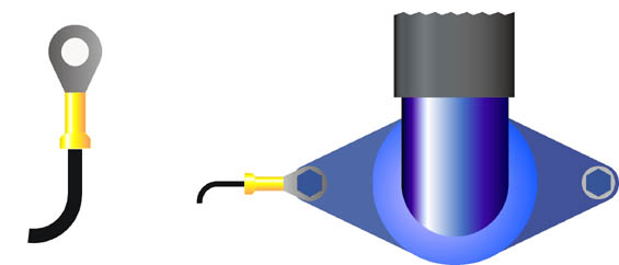
Figure 1a shows the Delta temperature probe. Figure 1b shows the typical mounting on the thermostat housing. Note that on engines with the thermostat on the engine coolant intake, the probe must be mounted near the outgoing engine (hot side) coolant.
Figure 1a Figure 1b
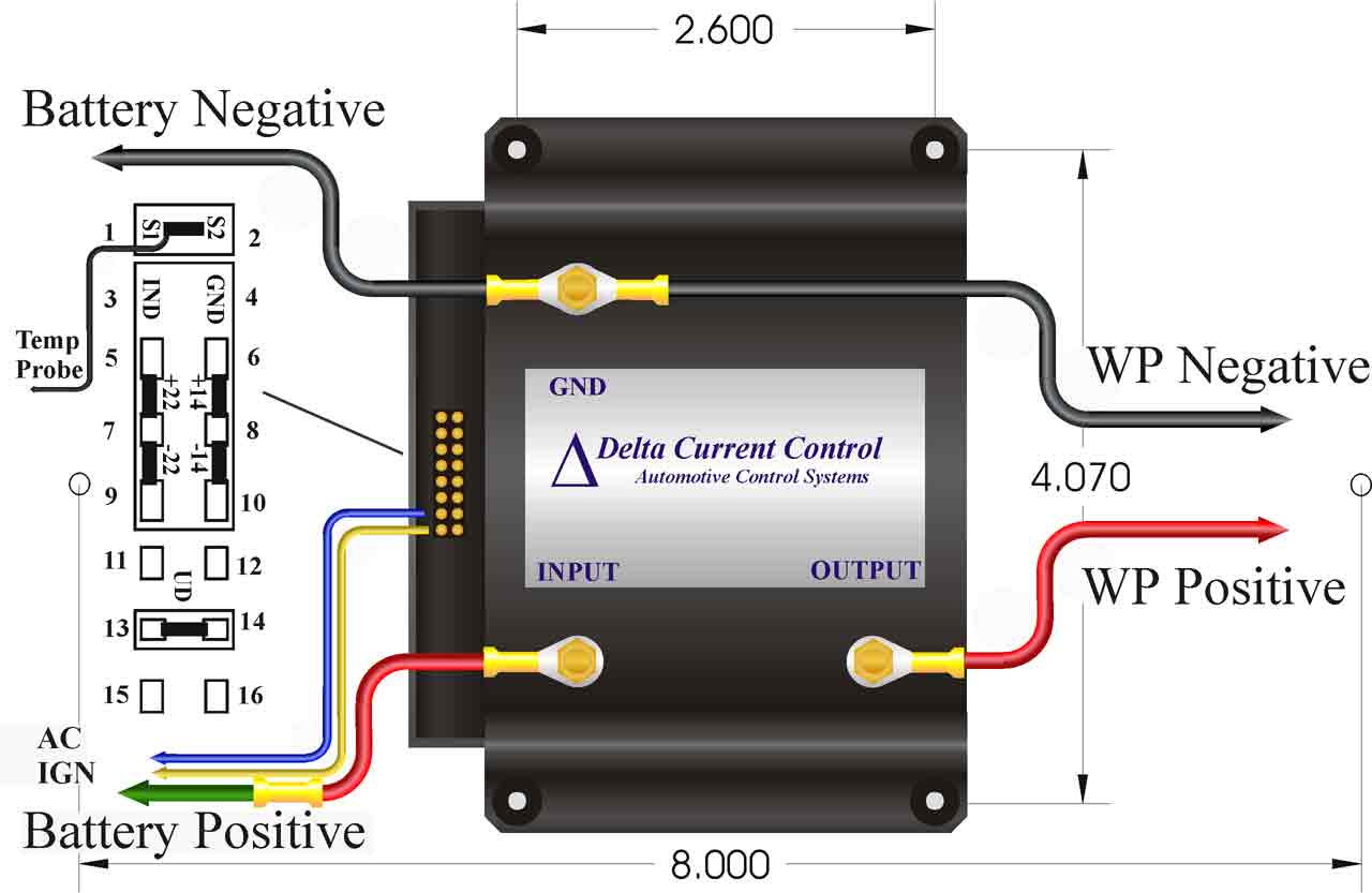
Control unit wiring
High current wiring
Plug the mounted sensor into pins 1, 2 of the control unit.
Using the supplied wiring loom, secure one connectored end of the red wire on the
Place one connectored end of the black wire on the GND terminal of the controller. Route the wire to the negative fan terminal, cut and trim the wire and install the female fastconnect harness. Connect the fan and water pump.
Place the connectored end of the remaining black wire on the GND terminal of the controller and secure both wires with one star washer and 6-32 brass hex nut. Route the wire to the negative battery terminal. Attach the 5/16 ring terminal and connect to the negative battery terminal.
Place the connectored end of the remaining red wire on the
Figure 2
|
CAUTION INSERTING A JUMPER ACROSS PINS 11 and 12 WILL DAMAGE THE CONTROL UNIT
|
|
Auxiliary wiring
|
|
148 |
158 |
166 |
173 |
180 |
187 |
194 |
202 |
212 |
|
|
(5,7) |
· |
· |
· |
||||||
| (6,8) |
· |
· |
· |
||||||
| (8,10) |
· |
· |
· | ||||||
| (7,9) |
· |
· |
· |
|
Parts List 1 control unit 1 engine temperature probe 1 high current wiring harness 2 fastconnect harnesses 1 low current wiring harness 1 fusible link 4 male fastconnects |
1 5/16 ring terminal 2 wire hold downs 3 internal star washers 3 6-32 brass nuts 6 # 6 self tapping screws 6 flat washers 3 zero ohm jumpers 4 3/16 rubber grommets |
Testing the unit
Start the car. If equipped with air conditioning, turn on the AC, the fan should run at 100%. Check the direction of air and coolant flow and reverse the fan and water pump input wires if necessary. Turn off the AC and let the engine warm up. The fan and water pump should run at the necessary speed to stabilize engine temperature.
LIMITED WARRANTY
Delta Current Control, hereon referred to as DCC, warrants to the first consumer purchaser that this DCC brand product, hereon referred to as the product, when shipped in its original container, will be free from defective workmanship and materials and agrees to, at its option, either repair the defect or replace the defective Product or part thereof at no charge to the purchaser for parts or labor for the time period(s) set forth below.
This warranty does not apply to any appearance items of the Product nor to any product the exterior of which has been damaged or defaced, which has been subjected to misuse, abnormal service or handling or which has been altered or modified in design or construction.
In order to enforce the rights under this limited warranty, the purchaser should follow the steps set forth below and provided proof of purchase to the servicer.
The limited warranty described herein is in addition to whatever implied warranties may be granted to purchasers by law. ALL IMPLIED WARRANTIES INCLUDING THE WARRANTIES OF MERCHANT ABILITY AND FITNESS FOR USE ARE LIMITED TO THE PERIOD"(S) FROM THE DATE OF PURCHASE SET FORTH BELOW. Some states do not allow limitations on how long an implied warranty lasts, so the limitation may not apply to you.
Neither the sales personnel of the seller nor any other person is authorized to make any warranties other than those described herein or to extend the duration of any warranties beyond the time period described on behalf of DCC.
The warranties described herein shall be the sole and exclusive warranties granted by DCC and shall be the sole and exclusive remedy available to the purchaser. Correction of defects, in the manner and for the period of time described herein, shall constitute complete fulfillment of all liabilities and responsibilities of DCC to the purchaser with respect to the Product and shall constitute full satisfaction of all claims, whether based on contact, negligence, strict liability or otherwise. In no event shall DCC be liable, or in any way responsible, for any damages or defects in the Product which were caused by repairs performed by anyone other than an authorized servicer. Nor shall DCC be liable, or in any way responsible, for any incidental or consequential economic or property damage. Some states do not allow the exclusion of incidental or consequential damages, so the above exclusion may not apply to you.
THE WARRANTY GIVES YOU SPECIFIC LEGAL RIGHTS. YOU MAY ALSO HAVE OTHER RIGHTS WHICH VARY FROM STATE TO STATE.
|
Warranty Period for this Product: |
Ninety (90) days parts and labor from date of purchase |
|
Where to obtain service: |
To locate an authorized DCC service center, contact DeltaCurrent Control at (408) 379 - 8951 |