FK-50P35
Fan and Water Pump Control Kit
Delta Current Control module
Installation
Setting the Temperature
The controller is set from the factory for use with a 180 degree thermostat, the set temperature, however, can be adjusted byway of the multiturn potentiometer. Each turn clockwise will raise the temperature approximately 3 1/2 degrees, each turn ccw will lower the temperature by the same amount. A total adjustment of +/- 35 degrees is possible.
Mounting the control unit
Find a flat surface in the engine compartment, the preferred area being the radiator support sheet metal near the battery. Drill four 1/8" holes either by the dimensions shown in figure 2 or by using the control unit as a template. Drill two more 1/8" holes at about 8" centers as shown in figure 2. If installed in a detailed engine compartment, insert the four grommets in the mounting holes of the control unit to protect painted surfaces. Mount the control unit using four self tapping screws and flat washers.
Delta fast response temperature sensor
Mounting the temperature sensor
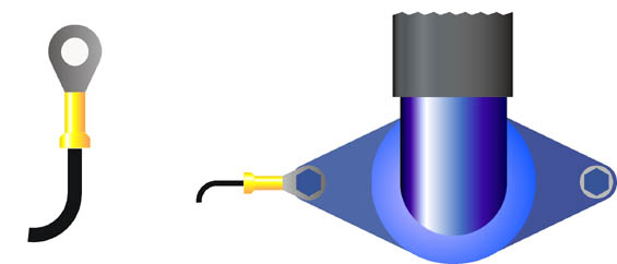
Figure 1a shows the Delta temperature probe. Figure 1b shows the typical mounting on the thermostat housing. Note that on engines with the thermostat on the engine coolant intake, the probe must be mounted near the outgoing engine (hot side) coolant.
Figure 1a Figure 1b
Control unit wiring
High current wiring
Plug the mounted sensor into pins 1, 2 of the control unit.
Using the supplied wiring loom, secure one connectored end of the red wire on the
Using the supplied wiring loom, secure one connectored end of the red wire on the wp terminal of the controller using one star washer and brass 6-32 hex nut. A snug fit is all that is needed (5-in-lb), Be careful not to overtighten. Route the wire to the positive water pump terminal, cut and trim the wire and install the butt connector to connect the water pump wiring.
Place one connectored end of the black wire on the GND terminal of the controller. Route the wire to the negative fan terminal, and negative water pump terminal cut and trim the wire and install the butt connector to connect the fan wiring.
Place the connectored end of the remaining black wire on the GND terminal of the controller and secure both wires with one star washer and 6-32 brass hex nut. Route the wire to the negative battery terminal. Attach the 5/16 ring terminal and connect to the negative battery terminal.
Place the connectored end of the remaining red wire on the input terminal of the controller and secure the wire with one star washer and brass 6-32 hex nut. Route the wire to the positive battery terminal. Attach the fusible link and connect to the positive battery terminal. Do not connect to the starter end of the battery cable or to the alternator. Use the supplied wire hold downs, along with two self tapping screws and flat washers to secure the wires.
Figure 2
 |
Auxiliary wiring
AC input
|
|
|
Parts List 1 control unit 1 radiator temperature probe 1 high current wiring harness 1 low current wiring harness 1 fusible link 2 controller to fan connectors |
1 5/16 ring terminal 2 wire hold downs 3 internal star washers 3 6-32 brass nuts 6 # 6 self tapping screws 6 flat washers 4 3/16 rubber grommets |
|
Testing the unit
Turn on the ignition, the wp should run at 20% power (about 5.2V) and the fan should run at about 3% power (about 2V) Let the engine warm, the fan and water pump should maintain the set temperature of the controller.
Start the car. If equipped with air conditioning, turn on the AC, the fan should run at 50 % power without the underdrive jumper and 100% with the jumper. Check the direction of airflow and reverse the fan input wires if necessary. Turn off the AC and let the engine warm up. The fan should run at the necessary speed to stabilize engine temperature.